Q100
Contents
Overview
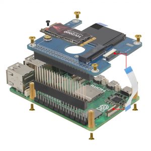
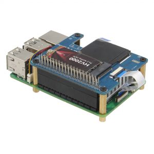
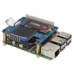
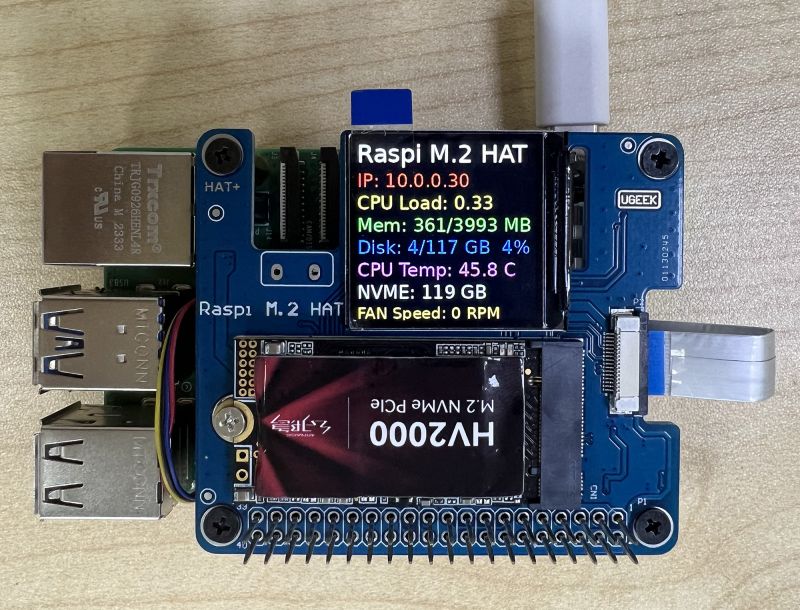
The Q100 is an expansion board similar to X1000. It has the function of PCIE to NVME ssd and also has an attached a 1.3" 240x240 Color TFT(ST7789 chipset), The TFT can display system and SSD status information, making it ideal for use as an additional display for NAS or media systems.
Geekworm PCIe to NVME Sets:
| Model | Compatible with | Position | NVMe M2 SSD Support | Matching Case | Other |
|---|---|---|---|---|---|
| X1000 | Raspberry Pi 5 | Top | 2230/2242 NVMe M2 SSD | P579 | |
| X1001 | Raspberry Pi 5 | Top | 2230/2242/2260/2280 NVMe M2 SSD | P579 | |
| X1002 | Raspberry Pi 5 | Bottom | 2230/2242/2260/2280 NVMe M2 SSD | P580 | |
| X1003 | Raspberry Pi 5 | Top | 2230/2242 NVMe M2 SSD | P579 / P425 / Raspberry Pi 5 Official case | |
| X1004 | Raspberry Pi 5 | Top | Dual 2280 NVMe M2 SSD | P579-V2 | |
| M300 | Raspberry Pi 5 | Top | 2230/2242 NVMe M2 SSD | P579 | |
| M400 | Raspberry Pi 5 | Top | 2230/2242/2280 NVMe M2 SSD | P579 | |
| Q100 | Raspberry Pi 5 | Top | 2242 NVMe M2 SSD | P579 | With 1.3" 240x240 Color TFT |
Features
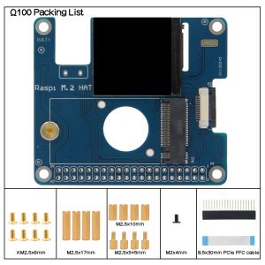
- NVMe Base PCB with M.2 Slot (M-Key NVMe SSD with 2242 sizes)
- With ACT LED Indicator(Flashing: Reading /Writing)
- With 40pin GPIO Header,it can supply power from GPIO,avoiding the problem of insuggicient power supply for ultra-large capactiy SSDs
- 1.3" 240x240 Color TFT (ST7789 chipset),The TFT can display system and SSD status information, making it ideal for use as an additional display for NAS or media systems.
- 'PCIe Pipe' Flat Flex Shielded Cable(50mm length FFC Shielded Cable),shielded cables can provide better PCIE performance, effectively solve the interference problem between PCIE and WIFI, and provide a more stable data link for SSDs.
PIN OUT
| PIN | Raspberry Pi Interface (BCM) | Description |
|---|---|---|
| SCLK | P11/SCLK | SPI clock line |
| MOSI | P10/MOS | SPI data line |
| CS | P8/CE0 | Chip selection |
| DC | P25 | Data/Command control |
| RST | NOT USE | Reset |
| BL | P27 | Backlight |
LCD and the controller
The ST7789VW is a single-chip controller/driver for 262K-color, graphic type TFT-LCD. It consists of 240 source line and 320 gate line driving circuits. The resolution of this LCD is 240 (H) RGB x 240(V), it supports horizontal mode and vertical mode, and it doesn't use all the RAM of the controller.
This LCD accepts 8-bits/9-bits/16-bits/18-bits parallel interface, that are RGB444, RGB565, RGB666. The color format used in demo codes is RGB565.
This LCD use a 4-line SPI interface for reducing GPIO and fast speed.LCD
LCD Working Protocol
Note: Different from the traditional SPI protocol, the data line from the slave to the master is hidden since the device only has display requirement.
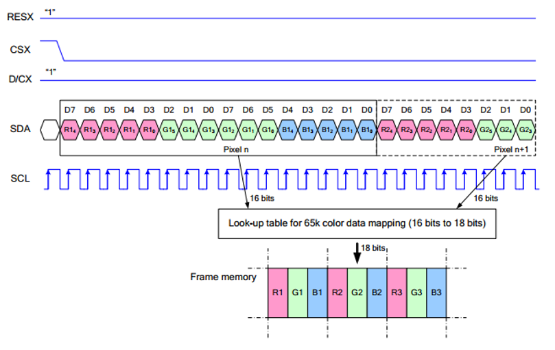
RESX Is the reset pin, it should be low when powering the module and be higher at other times;
CSX is slave chip select, when CS is low, the chip is enabled.
D/CX is data/command control pin, when DC = 0, write command, when DC = 1, write data
SDA is the data pin for transmitting RGB data, it works as the MOSI pin of SPI interface;
SCL worka s the SCLK pins of SPI interface.
SPI communication has data transfer timing, which is combined by CPHA and CPOL.
CPOL determines the level of the serial synchronous clock at idle state. When CPOL = 0, the level is Low. However, CPOL has little effect to the transmission.
CPHA determines whether data is collected at the first clock edge or at the second clock edge of serial synchronous clock; when CPHL = 0, data is collected at the first clock edge.
There are 4 SPI communication modes. SPI0 is commonly used, in which CPHL = 0, CPOL = 0.
User Manual
Only provides tutorials for running on Raspberry Pi OS as following
NVMe SSD boot tutorial
Reter to NVMe SSD boot with the Raspberry Pi 5
LCD display tutorial
1. Enable SPI interface
Reter to How to enable SPI
2. Install Library
PS: If you use the bookworm system, you can only use lgpio library, bcm2835 and wiringPi can't be installed and used.
BCM2835
#Open the Raspberry Pi terminal and run the following command
wget http://www.airspayce.com/mikem/bcm2835/bcm2835-1.71.tar.gz
tar zxvf bcm2835-1.71.tar.gz
cd bcm2835-1.71/
sudo ./configure && sudo make && sudo make check && sudo make install
# For more, you can refer to the official website at: http://www.airspayce.com/mikem/bcm2835/
WiringPi
#Open the Raspberry Pi terminal and run the following command
cd
sudo apt-get install wiringpi
#For Raspberry Pi systems after May 2019 (earlier than that can be executed without), an upgrade may be required:
wget https://project-downloads.drogon.net/wiringpi-latest.deb
sudo dpkg -i wiringpi-latest.deb
gpio -v
# Run gpio -v and version 2.52 will appear, if it doesn't it means there was an installation error

# Bullseye branch system using the following command:
git clone https://github.com/WiringPi/WiringPi
cd WiringPi
. /build
gpio -v
# Run gpio -v and version 2.70 will appear, if it doesn't it means there was an installation error
lgpio
#Open the Raspberry Pi terminal and run the following command
wget https://github.com/joan2937/lg/archive/master.zip
unzip master.zip
cd lg-master
sudo make install

# You can refer to the official website for more: https://github.com/gpiozero/lg
Python
sudo apt-get update
sudo apt-get install python3-pip
sudo apt-get install python3-pil
sudo apt-get install python3-numpy
#sudo pip3 install spidev
Download Examples
git clone https://github.com/geekworm-com/Q100.git
cd Q100
3. Run the demo
sudo python status.py
The results are as follows:
4. Auto-start when Power on
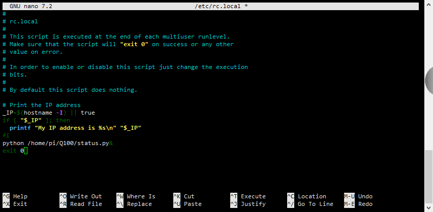
Configure the script to run automatically at startup
sudo nano /etc/rc.local
and python /home/pi/Q100/status.py& before exit 0 line
5. References:
Enable comment auto-refresher