Difference between revisions of "X708-Hardware"
Jump to navigation
Jump to search
| Line 2: | Line 2: | ||
[[File:X708-fn.jpg|none]] | [[File:X708-fn.jpg|none]] | ||
| − | + | 1. Power Jack and Connectors | |
{| class="wikitable" | {| class="wikitable" | ||
| Power input || 5Vdc +/- 5% , ≥3A | | Power input || 5Vdc +/- 5% , ≥3A | ||
| Line 18: | Line 18: | ||
* Don't power the Raspberry Pi via the Pi's type-C USB socket | * Don't power the Raspberry Pi via the Pi's type-C USB socket | ||
* X708 can be powered via the onboard DC jack or Type-C USB power socket | * X708 can be powered via the onboard DC jack or Type-C USB power socket | ||
| + | |||
| + | 2. 6-Pin Function Header | ||
{| class="wikitable" | {| class="wikitable" | ||
| Line 49: | Line 51: | ||
|} | |} | ||
| − | + | 3. How to connector external power switch | |
{| class="wikitable" | {| class="wikitable" | ||
! Pin No. !! Pin Description | ! Pin No. !! Pin Description | ||
| Line 64: | Line 66: | ||
! 4 | ! 4 | ||
| LED+ for power on, rebooting and shutdown | | LED+ for power on, rebooting and shutdown | ||
| + | |} | ||
| + | |||
| + | 4. Power button (Script for power mgnt installed) | ||
| + | {| class="wikitable" | ||
| + | ! Press and Release !! Raspberry Pi and X708 turn on | ||
| + | |- | ||
| + | ! Press and hold for 1~2 seconds | ||
| + | | System rebooting | ||
| + | |- | ||
| + | ! Press and hold for 3~7 seconds | ||
| + | | System shutting down | ||
| + | |- | ||
| + | ! Press and hold for >8 seconds | ||
| + | | Force shutdown | ||
| + | |} | ||
| + | |||
| + | 5. Function LEDs | ||
| + | {| class="wikitable" | ||
| + | ! LED Name !! Usage | ||
| + | |- | ||
| + | ! BAT | ||
| + | |- | ||
| + | ! LOW | ||
| + | | LED red on indicates battery low (≤3.0Vdc) or | ||
| + | |- | ||
| + | ! blue power button pressed | ||
| + | |- | ||
| + | ! (Jumper for ASD inserted) | ||
| + | |- | ||
| + | ! 5V | ||
| + | |- | ||
| + | ! OUT | ||
| + | | LED green on flashing indicates 5V power out | ||
| + | |- | ||
| + | ! and UPS powered by battery | ||
| + | |- | ||
| + | ! AC | ||
| + | |- | ||
| + | ! FAIL | ||
| + | | LED red on indicates AC power loss or PSU | ||
| + | |- | ||
| + | ! failure or PSU disconnected | ||
| + | |- | ||
| + | ! PWR | ||
| + | | LED blue indicates | ||
| + | |- | ||
| + | ! Stays on - Power on | ||
| + | |- | ||
| + | ! Blinks rapidly - system rebooting | ||
| + | |- | ||
| + | ! Blinks slowly - Shutting down | ||
| + | |} | ||
| + | |||
| + | 6. Fuel gauge - LED Indicator | ||
| + | |||
| + | Operation of Discharging | ||
| + | {| class="wikitable" | ||
| + | ! Capacity C (%) !! D1 !! D2 !! D3 !! D4 | ||
| + | |- | ||
| + | | C ≥75% || ON || ON || ON || ON | ||
| + | |- | ||
| + | | 50%≤C<75% || ON || ON || ON || OFF | ||
| + | |- | ||
| + | | 25%≤C<50% || ON || ON || OFF || OFF | ||
| + | |- | ||
| + | | 3%≤C<25% || ON || OFF || OFF || OFF | ||
| + | |- | ||
| + | | 0%<C<3% || Flashing || OFF || OFF || OFF | ||
| + | |} | ||
| + | |||
| + | Operation of charging | ||
| + | {| class="wikitable" | ||
| + | ! Capacity C (%) !! D1 !! D2 !! D3 !! D4 | ||
| + | |- | ||
| + | | Fully charged || ON || ON || ON || ON | ||
| + | |- | ||
| + | | 75%≤C || ON || ON || ON || Flashing | ||
| + | |- | ||
| + | | 50%≤C<75% || ON || ON || Flashing || OFF | ||
| + | |- | ||
| + | | 25%≤C<50% || ON || Flashing || OFF || OFF | ||
| + | |- | ||
| + | | C<25% || Flashing || OFF || OFF || OFF | ||
| + | |} | ||
| + | |||
| + | 7. Pins and GPIO used | ||
| + | |||
| + | {| class="wikitable" | ||
| + | ! Pin No. !! Usage | ||
| + | |- | ||
| + | ! 2, 4 | ||
| + | | +5V power supply | ||
| + | |- | ||
| + | ! 3, 5 | ||
| + | | I2C for RTC and battery fuel-gauge systems | ||
| + | |- | ||
| + | ! 6 | ||
| + | | Ground | ||
| + | |- | ||
| + | ! 29 | ||
| + | | GPIO5 for power management | ||
| + | |- | ||
| + | ! 32 | ||
| + | | GPIO12 for power management | ||
| + | |- | ||
| + | ! 33 | ||
| + | | GPIO13 for power management | ||
| + | |- | ||
| + | ! 31 | ||
| + | | GPIO6 for AC power loss detection | ||
| + | |- | ||
| + | ! (Jumper for PLD inserted, High=power loss, | ||
| + | |- | ||
| + | ! Low=Power supply normal) | ||
|} | |} | ||
Revision as of 12:01, 25 July 2020

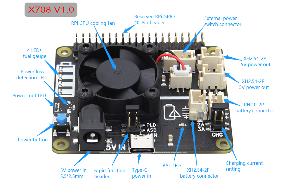
1. Power Jack and Connectors
| Power input | 5Vdc +/- 5% , ≥3A |
| DC Power Plug Size | 5.5*2.5mm |
| USB power in socket | Type-C |
| UPS power output | 5.1Vdc 8A |
| Power output connector | XH2.54mm 2pin |
- X708 powers the Raspberry Pi via the 40-pin header (Pin 2 & 4)
- Don't power the Raspberry Pi via the Pi's type-C USB socket
- X708 can be powered via the onboard DC jack or Type-C USB power socket
2. 6-Pin Function Header
| Jumper Name | Usage |
|---|---|
| PLD
(Power loss detection) Pin 1&2 |
|
| AON
(Auto power-on) Pin 3&4 |
|
| ASD
(Auto shutdown) Pin 5&6 |
1. Battery voltage must be >3Vdc
2. Insert the battery into the holder
3. Wait 3 seconds then insert the jumper
4. If the jumper inserted before battery, remove battery & jumper then repeat step 1, 2 and 3.
|
3. How to connector external power switch
| Pin No. | Pin Description |
|---|---|
| 1 | Power on/off control connecting to switch |
| 2 | Ground |
| 3 | LED+ for battery low indicator |
| 4 | LED+ for power on, rebooting and shutdown |
4. Power button (Script for power mgnt installed)
| Press and Release | Raspberry Pi and X708 turn on |
|---|---|
| Press and hold for 1~2 seconds | System rebooting |
| Press and hold for 3~7 seconds | System shutting down |
| Press and hold for >8 seconds | Force shutdown |
5. Function LEDs
| LED Name | Usage |
|---|---|
| BAT | |
| LOW | LED red on indicates battery low (≤3.0Vdc) or |
| blue power button pressed | |
| (Jumper for ASD inserted) | |
| 5V | |
| OUT | LED green on flashing indicates 5V power out |
| and UPS powered by battery | |
| AC | |
| FAIL | LED red on indicates AC power loss or PSU |
| failure or PSU disconnected | |
| PWR | LED blue indicates |
| Stays on - Power on | |
| Blinks rapidly - system rebooting | |
| Blinks slowly - Shutting down |
6. Fuel gauge - LED Indicator
Operation of Discharging
| Capacity C (%) | D1 | D2 | D3 | D4 |
|---|---|---|---|---|
| C ≥75% | ON | ON | ON | ON |
| 50%≤C<75% | ON | ON | ON | OFF |
| 25%≤C<50% | ON | ON | OFF | OFF |
| 3%≤C<25% | ON | OFF | OFF | OFF |
| 0%<C<3% | Flashing | OFF | OFF | OFF |
Operation of charging
| Capacity C (%) | D1 | D2 | D3 | D4 |
|---|---|---|---|---|
| Fully charged | ON | ON | ON | ON |
| 75%≤C | ON | ON | ON | Flashing |
| 50%≤C<75% | ON | ON | Flashing | OFF |
| 25%≤C<50% | ON | Flashing | OFF | OFF |
| C<25% | Flashing | OFF | OFF | OFF |
7. Pins and GPIO used
| Pin No. | Usage |
|---|---|
| 2, 4 | +5V power supply |
| 3, 5 | I2C for RTC and battery fuel-gauge systems |
| 6 | Ground |
| 29 | GPIO5 for power management |
| 32 | GPIO12 for power management |
| 33 | GPIO13 for power management |
| 31 | GPIO6 for AC power loss detection |
| (Jumper for PLD inserted, High=power loss, | |
| Low=Power supply normal) |
Enable comment auto-refresher
Anonymous user #8
Permalink |
Walker
Anonymous user #15
Permalink |
Lisa
Anonymous user #15
Permalink |
Lisa
Anonymous user #16
Lisa
Anonymous user #14
Permalink |
Anonymous user #13
Anonymous user #14
Anonymous user #13
Permalink |
Lisa
Anonymous user #12
Permalink |
Lisa
Anonymous user #10
Permalink |
Lisa
Anonymous user #10
Permalink |
Lisa
Lisa
Anonymous user #10
Lisa
Anonymous user #9
Permalink |
Lisa
Anonymous user #8
Permalink |
Lisa
Anonymous user #7
Permalink |
Anonymous user #3
Permalink |
Anonymous user #4
Anonymous user #5
Anonymous user #5
Xiali
Anonymous user #2
Permalink |
Anonymous user #5
Anonymous user #6
Anonymous user #11
Anonymous user #1
Permalink |